How to Put an Engine on an Engine Stand Without Tipping It
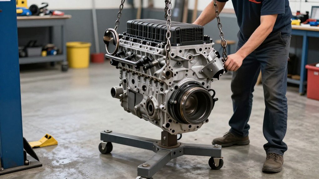
To put an engine on a stand without tipping it, verify the stand’s rating exceeds the engine’s weight and inspect its mount and casters. Drain fluids, remove obstructing accessories, and use correctly sized bolts.
Set the stand on a level, clear floor, lock every caster, and confirm the base won’t rock.
Keep the engine centered over the base with a load-leveler, lower it slowly, and tighten bolts evenly to specification.
More checks can prevent mishaps.
Engine Stand Load Limits
Before mounting the engine, verify that the stand’s rated capacity exceeds its actual weight; for example, use a 2,000-pound stand only for engines under that limit, and never exceed the manufacturer’s maximum. Then confirm stability features support the load.
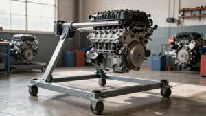
A wide H-shaped base on a 2,000-pound model can reduce tipping risk. Use only a stand rated for your engine’s mounting compatibility; an unsuitable fit can create leverage forces that act like overloading even when the engine’s weight stays within capacity. Adjust the mounting arms and rotating head for the engine size so the load remains centered over the base.
Before loading, inspect casters and verify each lock holds firmly. Loose or nonlocking casters can let the stand move and destabilize it under rated load.
Engine-to-Stand Hardware
Use engine-to-stand bolts that match the block’s specified hole size and torque requirements, and check that the stand’s hardware pattern fits your engine type, such as SB-CHEVY, BB-CHEVY, or GEN-1 SB-CHEVY. Secure the mounting plate to the block before lowering the engine.
Lower it, align the plate and stand holes, then insert bolts without forcing them; binding can shift the load and increase tipping risk.
- Tighten bolts evenly; uneven clamping can compromise stability during rotation.
- Don’t overtighten; distorted plates may destabilize the mounted engine.
- Confirm every fastener meets the block manufacturer’s torque specification.
- Verify the mounting pattern matches your engine before loading.
- Recheck the rotating-mount lock after torquing, before moving the stand.
Keep the load centered, and pause if any connection feels loose.
Step 1: Drain Fluids and Remove Accessories
With the mounting hardware verified, drain the engine’s oil, coolant, and any fuel, then let it sit until no fluids leak; removing that shifting weight helps keep the load balanced during placement. Disconnect and remove the battery, wiring harness connections, fuel lines, and hoses before lifting; none should remain to snag or pull the engine off balance. Remove accessories that create uneven mass or obstruct lowering, including the alternator, starter, power-steering pump, A/C compressor, and, when they interfere, exhaust manifolds or headers.
Clean the engine face and mounting area so the adapter plate seats flush; this supports accurate alignment and reduces the chance of tilting while you position the stand. Keep loose parts and lines clear of the lifting path, and cap open fuel connections.
Step 2: Level the Stand’s Footing
On a level, debris-free garage floor, position the engine stand so every foot makes firm contact and the base doesn’t rock.
Use a straightedge or bubble level across the H-shaped or wide base to confirm it sits evenly before you lower the engine onto the mounting plate. If you find a tilt, stop and correct the footing; don’t rely on partial support or accept rocking.
Lock all casters before mounting so the stand can’t drift while you align and fasten the plate. This keeps its position stable as you work. On an uneven floor, reposition the stand on a truly flat surface or use proper shims under the feet, ensuring each remains securely supported.
After you adjust the stand’s height or arms, or change mounting heads, check the level again. Even a small angle change can shift the center of gravity and reduce overall stability.
Step 3: Position a Load-Leveler
Before lowering the engine, position the load-leveler so the suspended engine’s weight stays directly over the stand’s center of gravity. Place the stand on the level, debris-free surface established in the previous step; then inspect the leveler and its lifting connections before applying load.
Adjust the leveler to keep the engine level at the height where you’ll lower it. A level engine is less likely to shift suddenly or pull the stand off balance as you transfer weight. Maintain equal, steady hoist tension throughout the movement, and make only small, controlled angle corrections with the leveler when needed.
Pause if the engine swings; stabilize the load before continuing, and never stand beneath a suspended engine. Keep the hoist controls within reach at all times.
Step 4: Align Engine to Head
Once the engine is stable at the correct height, lock the stand’s casters on a level, debris-free surface and align the mounting plate with the block’s bolt pattern.
Use the engine’s specific pattern to position the head; keep the plate centered and match each mounting hole before lowering the engine. If the head adjusts, rotate it until the engine sits square, not angled.
Keep the load level as you guide the block toward the plate.
Lower the engine, watching alignment. Don’t force it into place; resistance can signal a mismatch, and pushing may shift the center of gravity and increase tipping risk. Once the plate seats, insert the bolts and tighten them to torque before adding support or handling the engine.
Step 5: Verify Mounting Bolt Clearance
Check bolt clearance before lifting: confirm the stand’s mounting holes match the block’s bolt pattern and that the bolts can pass through without binding or forcing the plate out of alignment.
Also, check the space behind and around the block, especially near studs, exposed threads, and ribs. Confirm no feature will contact the plate or force the engine to approach at an angle; uneven contact can lift one side and increase tipping risk.
Set adjustable arms and head to the block’s required height and width, then verify each bolt enters its matching hole smoothly without stretching or misalignment. After attaching the plate, visually confirm every bolt is fully inserted and engaged, with none touching the stand structure. Correct interference before safely lifting the engine.
Step 6: Torque Mounting Bolts Evenly
With the mounting holes aligned and each bolt seated correctly, tighten the bolts gradually in a star or cross pattern.
Before tightening, confirm you’ve positioned the stand on a level, debris-free surface and fitted the rated mounting plate. Work in stages: snug each bolt, then torque them to the engine or fastener manufacturer’s specified values. Alternate across opposing bolts so the plate loads evenly and the block doesn’t cant or shift to one side.
Don’t fully tighten one corner while others remain loose; uneven loading can disturb the engine’s placement. Use a calibrated torque wrench and the correct sequence for your plate and engine configuration. Once every bolt reaches specification, recheck each one for proper tightness.
Before you move or rotate the assembly, verify that the stand’s rotation and locking mechanism is engaged. Keep clear of the engine’s path and control movement deliberately throughout.
Check Mounting Plate Flex
Before lifting, verify that the mounting plate fits the engine’s bolt pattern and supported mounting points, then inspect it for cracks, rust, or bending around the fasteners. Press the plate gently and watch the bolt holes and plate edges for movement. Even slight flex can shift the engine as you lower it, changing its balance and raising tip risk.
A loose fit can concentrate the load and encourage bending. Tighten each mounting bolt evenly to the manufacturer’s torque specification so the plate won’t spring under load.
After you place the engine, apply light hand pressure and observe the plate edges again. Don’t proceed if you see continued movement, distortion, or the fastener area can’t support the load.
Caster Locks Won’t Engage
Even a sound mounting plate can’t prevent a tip if the stand’s casters move during installation. Before loading, verify the floor is level and debris-free; all six swivel casters must contact it evenly for their locks to engage. Inspect each lever for debris, rust, or bends; clean it, then confirm a firm lock securely.
| Check | Action |
|---|---|
| Floor | Level, clear, even contact |
| Lever | Clean; inspect for damage |
| No-load test | Roll slightly; lock each caster |
| Load position | Center weight over H-base |
| Failure | Replace caster or change stand |
After centering the engine over the H-shaped base, recheck locks: an off-center load may prevent them from gripping the floor. If any lock still fails, stop; don’t lower the engine onto the mount.
Replace damaged casters or use another stand, because free-swiveling movement raises tipping risk.
Protect Exposed Engine Openings
Protect exposed engine openings as soon as the block is seated flush on the stand. Cap intake ports, cylinder bores, and crankcase vents immediately with clean plugs, caps, or shop towels. This keeps debris out while you finish positioning the engine.
Lower the engine slowly and keep the block level so the mounting plate aligns without shifting, which could strain or tip the stand. Install the specified engine-to-stand bolts, using the correct size and torque listed in the stand’s instructions. Confirm the block remains flush before you remove any protective coverings.
Lock the casters before you release the hoist or adjust the engine; verify every lock engages, especially on stands with multiple swivel casters. Keep the floor and surrounding work area clear of debris.
Conclusion
Before rotating the engine, verify the stand’s load rating, secure every mounting bolt, and confirm the footing is level and the casters are locked. Use a load-leveler to control the engine’s position; stop if the plate flexes or any connection shifts. Keep hands clear of pinch points, and cap exposed openings.
If the stand feels unstable, lower the engine and correct the setup before proceeding. Don’t rely on force or balance alone to keep the load safe.