How to Use an Engine Load Leveler to Tilt and Clear the Bay
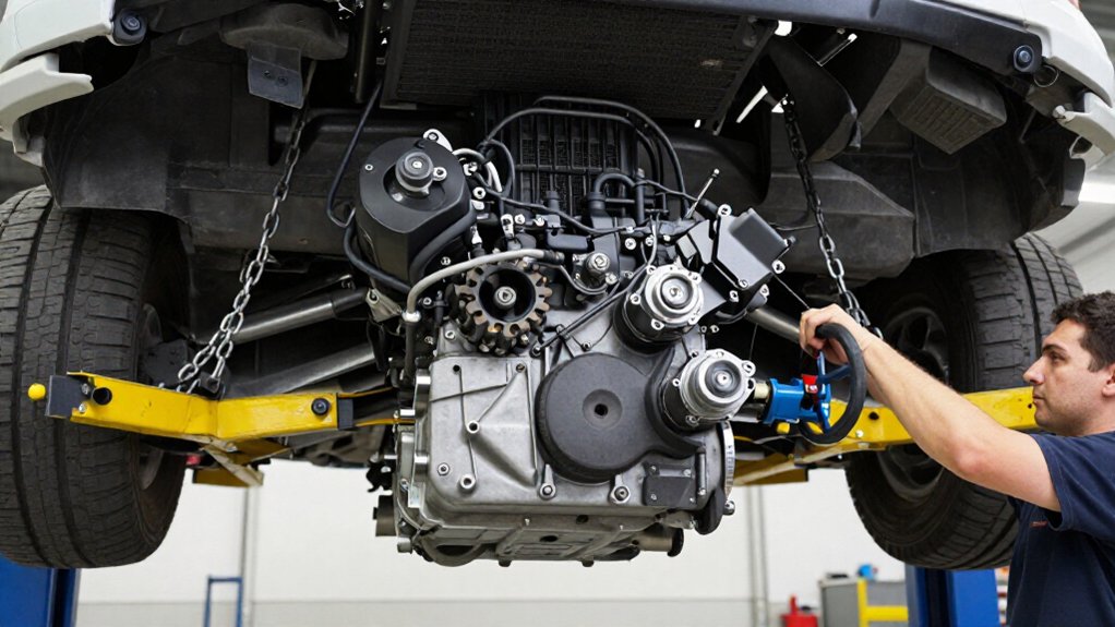
Before lifting, confirm the complete suspended load stays within your leveler’s rating, and attach it only to engine-specific lifting points.
Inspect the center pin and retainers, lubricate the lead screw, and secure all plates and chains.
Protect the radiator support, keep the engine low, and crank in small increments while watching firewall, hoses, wiring, and oil pan clearance.
Lower the transmission end gradually; stop if anything binds or shifts.
Next, learn how to verify each adjustment.
Load Leveler Capacity Limits
Before attaching an engine, check the leveler’s rated capacity; for example, the Powerbuilt® 1500 lb engine leveler (part #640470) is designed for engine-and-transmission combinations weighing up to 1,500 pounds. Keep the complete suspended load within that limit, including the engine, transmission, adapters, chains, and other hardware. Don’t exceed the rating during tilting; changing the angle alters forces on the supporting structure, so a load that seems manageable while level may become unsafe.
Confirm that your hoist can accommodate the leveler’s added height and geometry, and preserve enough clearance to control the angle without forcing the load. If you can’t verify the combined weight or safe tilting forces, stop. Check the leveler’s manual or contact its manufacturer before attempting an in-bay tilt. Reassess the setup whenever you change components, and don’t rely on estimates that omit attached equipment. Stay within every tool’s rated limit throughout the operation. Use measured weights whenever practical, not guesswork.
Engine-Specific Attachment Points
After confirming the total load stays within the leveler’s rating, attach it only to engine-specific lifting points that match the manufacturer’s intended load path, typically on the engine block and, when required, the transmission case. Secure every bolt and washer fully before lifting; don’t substitute improvised contact points, which can concentrate force or shift the engine.
- Match the leveler’s mounting pattern to the engine’s specified pickup locations; a four-point system may span the block and transmission case.
- For LS/LT-style engines, use a compatible valley-tray attachment when the leveler is designed for that setup.
- As you raise or lower, turn the hand crank or ratchet gradually to fine-tune tilt and monitor clearance.
Keep the load balanced, and stop if hardware loosens or anything shifts unexpectedly.
Step 1: Protect the Radiator Support
As you guide the suspended engine past the radiator support, use the leveler’s hand crank to tilt it just enough for clearance, then return it to level once the front mounts pass. Keep hoist movement slow and make angle adjustments while watching the support, radiator brackets, hoses, wiring, and bay openings. The leveler lets you fish the engine through the opening without striking the firewall or forcing the assembly against sheet metal.
Maintain a clear view of contact points; pause if anything shifts, catches, or approaches the support. In tight bays, adjust hoist-chain length as needed to complement the leveler’s height and provide room for the required arc. Don’t use the tilt mechanism to drag the engine sideways or overcome resistance.
Step 2: Fit Leveler to Lift Plates
With radiator-support clearance in mind, bolt the leveler’s lift plates to the engine’s designated mounting points, such as the block or valley area, or the transmission case specified by the system.
For an LS- or LT-specific system, fit plate hardware to the valley tray as designed; don’t omit supplied fasteners. Seat every plate fully and tighten bolts to the manufacturer’s specification. Position chains or rigging correctly on the plates; secure each connection and remove twists.
Verify four-point mounting and firm attachment before connecting the hoist. Check the leveler’s rated capacity against the engine and attached components; never exceed it. Inspect plates, fasteners, chains, and hooks for damage or looseness. Keep people clear of the suspended load during setup. Confirm the assembly feels stable.
Step 3: Lower the Transmission End Gradually
Once the hoist supports the engine and transmission, tilt the engine only enough to begin guiding the transmission end down, then pause to check that the tail clears the tunnel edges.
Use the leveler’s hand crank in small increments to lower the transmission end. These adjustments let you guide the tail into the tunnel without impact or binding. Keep the engine-to-transmission alignment steady throughout; don’t let the assembly swing or drag across mounts and crossmembers.
When clearance is tight, pause after each adjustment and confirm the transmission remains free. Avoid sudden angle or height changes, and keep the load supported. Continue in controlled steps until the transmission reaches position. Then carefully return the leveler toward a near-level angle before final mounting and alignment checks.
Step 4: Check Firewall Clearance as It Tilts
Before increasing the tilt, check that the hoist and leveler can clear the firewall and radiator support at the engine’s steepest angle.
Before lifting, visualize the engine’s path and confirm the hoist-and-leveler combination has room through the full tilt. Keep the engine low while you use the leveler’s hand crank for smooth, controlled angle changes; you can stop immediately if the nose or oil pan approaches either surface. Recheck clearance at each small crank or ratchet position: even slight changes can swing the block inches toward the firewall.
Adjust the angle to clear the tight area, then level the engine back out for final alignment. With engine and transmission together, tilt only enough to guide the transmission into the tunnel without engine-front contact.
Step 5: Confirm Cable Tension Before Tilting
Check that the leveler’s cable or chains are evenly tensioned before tilting the engine; slack on one side can make the load rotor take up unevenly and cause a sudden, jerky swing. Verify the cable runs consistently around the drum or rotor, following your leveler’s design, including any specified crossing-and-locking path.
Before using a worm-gear adjustment, confirm tension, then turn the crank in small increments; feel for smooth, steady resistance. Keep your hands and body clear of swinging stops and engagement parts. Recheck tension immediately before the first tilt change.
Watch the suspension and engine as you begin: if the engine shifts before you command an angle change, stop, stabilize the load, and inspect cable or chain tension before continuing. Resume only after rechecking tension before resuming any tilt.
Step 6: Cap Exposed Screw Threads
Keep cap-screw threads out of pinch points and the engine’s path as it tilts; exposed threads can snag or abrade slings and straps or catch on nearby components. You should use a leveler setup that keeps threaded portions covered near contact points. Seat each cap screw or bolt fully so its head or nut covers threads.
If hardware near the bay opening or crossmembers protrudes, replace or shorten it to stay within the intended footprint. Before lifting, visually check that no protruding threads align with the radiator support, firewall, subframe, or tunnel edges. Turn the hand crank or ratchet smoothly, and keep the engine-transmission assembly controlled so it can’t shift hardware into surrounding parts. Stop if contact develops; reset the hardware before continuing, and inspect it again.
Verify Oil Pan Clearance
With the hoist supporting the engine, use the leveler to verify oil pan clearance at both the level starting angle and the angle needed to approach the bay.
Keep the hoist loaded as you turn the crank in small increments. Stop before contact; visually and physically check pan clearance against the crossmember or subframe after each adjustment. Focus on the closest point, a sump corner or lowest edge: pitch changes can swing it inches.
Measure or mark the gap at the tightest orientation so you can reproduce the angle. If clearance is tight, stop and re-angle the engine until the pan passes without striking the bay. Once clear, return it to level. Don’t lower into position until you’ve confirmed clearance during approach.
Inspect the Leveler’s Center Pin
Before lifting, inspect the leveler’s center pin for straightness, wear, and proper retention; it’s the pivot that controls smooth, incremental tilt adjustments under load.
| Check | Action |
|---|---|
| Pin and surfaces | Check for scoring, cracks, rust, or bending. |
| Retention | Confirm fasteners and retainers are tight and seated. |
Verify the pin seats fully and has no excessive play. Damage or looseness can make it wobble, bind, or jump during fine adjustments, risking control as you clear the firewall or radiator support.
With the engine supported, move the manual adjustment through its intended range. It should respond incrementally without unusual resistance. If movement is erratic or retention is loose, don’t lift; correct the issue and reinspect. Keep hands clear of pinch points, and maintain secure engine support throughout.
Lubricate the Lead Screw
To keep tilt adjustments smooth, wipe grit from the lead screw, then apply a light coat of manufacturer-recommended oil or grease without over-greasing. Before use, check the screw and remove old, gritty residue to prevent abrasive wear and jerky movement. Use the manufacturer’s specified lubricant and viscosity; excess grease can trap debris.
With the load securely supported, turn the hand crank through its full range to spread lubricant along the threads. Keep your hands clear of pinch points, and make small tilt adjustments while monitoring the engine. During a long engine-out or engine-in cycle, stop if cranking feels gritty or slows.
Support the load, clean and relubricate the screw before continuing. Don’t force a binding mechanism; correct the cause first before you resume work.
Conclusion
Before tilting the engine, confirm the leveler’s rated capacity and use the engine maker’s approved attachment points. Protect the radiator support, secure the lift plates, and inspect the center pin and lead screw.
Raise the engine only enough to clear obstructions, then lower the transmission end gradually while watching the oil pan and surrounding parts. Cap exposed screw threads to prevent damage. Stop if anything shifts, binds, or contacts the bay; don’t force the lift.